Thanks the United States for donating 2.5 million doses of the Moderna COVID-19 vaccine to Taiwan
Specification:
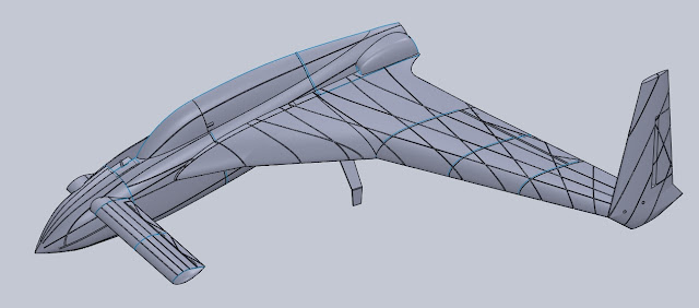
Wingspan: 1200mm
Weight (without battery): 950g
Printing material: PLA
File download: https://www.thingiverse.com/thing:4881634
I tried many settings of Lw-PLA , and two different brand (colorfabb and eSun), but there was no way to solve stringing issue. Unless the whole design is optimized for this material, Lw-PLA is not recommended.
You can use PLA or PETG. I use 3Dlabprint's Poly-Air, which is also a type of PLA, but its characteristics are optimized for single-layer printed RC aircraft. My experience is that its hardness and viscosity between layers are indeed much better than ordinary PLA.
***The plane has not yet been tested***
Due to COVID-19, Taiwan is currently in epidemic warning level of Level 3, and we are prohibited from public areas including the flight field.
I have no way to test this model, so there is no guarantee that it will work properly.
Need to know before assembling:
1. My model seperate the skeleton and the shell into two files, instead of making a single .stl file like the commercial models. So please watch this video first to know how to slice:
https://youtu.be/owgi07X3zd0
2. Printer settings. This part may be a bit complicated if you have never maked a 3D printing RC plane, and it requires multiple attempts. You can refer to the following instructional video,
3. If you have never assembled a 3D printed RC plane, or even play with a RC plane, please don't try it. This plan already belongs to high-level players to be able to complete. At the beginning of my design, it was purely my own fun. Many parts of it need to be modified manually, which is not as complete as commercial products. So please be mentally prepared before making it.
4. CA glue and CA glue accelerators are required for assembly. Many people have never heard of CA glue accelerators, and it is difficult to explain it at once. Anyway, go to eBay to search for it, and you will know the characteristics when you buy it and use it. Very easy to use...make the super glue really super and strong.
5. File naming principle: For the convenience of printing, this aircraft is cut into several sections to print.
frame-xx :fuselage, wing-xx: wing, hrz-xx: horizontal wing, ele-xx: elevator, ail-xx: aileron, vert-xx: vertical wing. Clip is the latch of the canopy.
xx is the section number. -skt is the skeleton, and -suf is the surface.
The extension .3mf is the project file of cura, which is used for reference settings. If there is -miro, it is the other side. If not, please use the built-in mirroring function of CURA.
-all: means there are on both sides.
.3mf, the CURA printing setting, the most important is to look at the number of the top layer and bottom layers. Sometimes, in order to increase the strength, there are one , two or not. otherwise, the skeletons wall thickness is set between 1-3.
Assemble the fuselage:
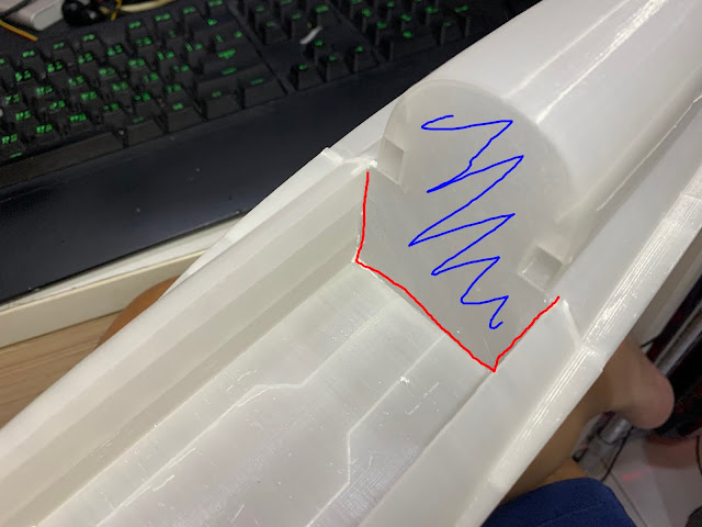
This part needs to be cut below as in the photo, and the actual cutting range depends on the tire you use and the size of the retract servo.
Please install the retract ans rudder servo on the adapter board (retract servo mount.STL), and then fix it with hot melt.
There are side skirts on the fuselage joints to facilitate gluing, but some parts are not easy to handle because of the 3D structure, so you need to refer to the photos to cut off the extra parts and glue them together. If I missed photos, please be prepared for it.
This is a installation photo of the cockpit cover latch. There is no spring inside, so before flight, please fix the stick with paper tape to avoid loosening during flight.
C.G. setting:
The picture below was found on the Internet, and I am not sure if it is correct. But the final C.G. of my design will almost be in this position. Please report the correct position after your test.
Rudder:
ince the vertical is located at the very end of the main wing, the control of the rudder must be equipped with an independent servo, and then a long extension wire be used. This increased weight may not be suitable, especially the rudder is almost useless when flying, so finally I omit the rudder from the design.


沒有留言:
張貼留言